Wiring diagram for blower motor resistor 5af72bbdca896.gif.
May 9, 2023 · The wiring diagram for a blower motor resistor consists of three main components: the power supply, the ground, and the blower motor. The power supply is the source of electricity for the blower motor, and the ground is the return path for the current.
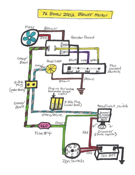
Mar 21, 2010 · Hooked the brown wire to the positive battery terminal, the yellow to the negative, I heard the fan spin- so, the fan blower is operational. Step 2. If that works reconnect them. Turn the ignition on. Take the wire, should be yellow, off of the resister on the heater box and ground it. The fan should also spin. 3Ø WIRING DIAGRAMS 1Ø WIRING DIAGRAMS Diagram ER9 M 3~ 1 5 9 3 7 11 Low Speed High Speed U1 V1 W1 W2 U2 V2 TK TK Thermal Overloads TWO SPEED STAR/DELTA MOTOR Switch M 3~ 0-10V 20V 415V AC 4-20mA Outp uts Diagram IC2 M 1~ 240V AC 0-10V Outp ut Diagram IC3 M 1~ 0-10V 4-20mA 240V AC Outp uts These diagrams are current at the time of publication ...All control of the blower operation is done using the ground side of the circuit. You should always have 12 volts at the brown wire of the blower connector. You won't get 12 volts by metering the brown and orange leads, if the ground is defective. There aren't any HVAC grounds in the ground point on the left side.Oct 19, 2010 · Like. abernut Discussion starter · #10 · Oct 21, 2010. That indeed was the correct wire. I plugged it in to the blower, got back in the cab, turned the key and with a little bit of hesitation turned the heater knob to Max. The **** eating grin I had on my face when I heard the blower fire up was priceless.:2thumbsup:
Engine: 350 cam, boltons/350/cam boltons. Transmission: 700r4/700r4/M6. Axle/Gears: 3.73/3.43/3.43. Heater Blower Motor, Resistor, Relay, and more... Heater Blower Motor Information. So, after searching a million threads and asking a million questions I finally got the information I needed. But it took a very long and rather boring time to do ...BLOWER RESISTOR BLOCK WIRING DIAGRAM (NEGATIVE SWITCH CONTROL)Sa video na ito ay ipapakita ko sa inyo ang wiring diagram ng blower resistor block. Kaya't pan...Re: 72 C10 heater/ A/c wiring diagram. Just rebuilt my factory AC and here is what I found - I had the opposite problem than you - my low and med speeds weren't working but high was. The high side is your relay and it is mounted to the heater box behind the glove box. The low and med speeds are resistor related.
Jun 19, 2008 · No, the resistor will easily come off and rep-connect. Just trace the red/back from the resistor and you'll find it plugs into the fan motor. That is the easiest part of this repair, the splicing of wires is the hardest. As smith mentioned, pay attention to the wire order so you don't do what I did first. Dec 14, 2022 · To bypass the blower motor resistor, you can use a one-wire relay. Insert one end of the relay wire into the blower motor resistor point and to the other end too. You should only bypass a blower motor resistor in a short time or emergency only. However, it is not recommended to bypass a blower motor resistor, as doing so can cause damage to the ...
Blower motor wiring diagrams for three or four speed systems. Carmakers use these three common wiring methods to supply power and ground to the blower motor in a manual system using a blower motor resistor.On a 66 heater (no ac car) the blower fan power is fed via the orange wire from the heater motor. That wire goes back through the bulkhead connector, so check and clean that connection. From there it goes to the heater blower resistor, inside the car, on top of the heater box under the glove box.Aug 3, 2023 · Figure 1 If your blower or fan motor runs at full speed regardless of the setting you have it on there is a very good chance your resistor is bad. The resistor is located below the blower motor in the cabin air box (red arrow). Please see our article on blower motor replacement for additional assistance on removing the motor. The heater blower motor stops working ? Testing the electrical circuit would be the proper way to diagnose . Looking at a wiring diagram an using a DMM - digital multi-meter , an doing amp draw test on the blower motor . The PRND321 an blower motor probably share a ground or power point . Looking at a wiring diagram for both circuit's would ...1992 Plymouth Grand Voyager LE 3.3L V6 A604/ 41TE 4 speed with about 353,000 miles. There is a 30A fuse (J15) for the front blower, but it shouldn't blow unless there is a problem. The front blower speeds are controlled by a blower resistor in MTC vehicles and a solid-state module in ATC vehicles.
Nov 11, 2008 · If the same as on a 93 the wiper motor has two connectors. Connector A (motor): wiper switch to motor (high) - dark brown / orange. wiper switch to motor (low) - white. ground - black. Connector B (park switch): wiper switch to motor (park and return) - red. wiper switch to motor (park return) - black. ground - black.
1 4 Watt Resistor Footprint. January 06, 2017. The Size Of Smd Ics Electronics Repair And Technology News. Common Resistance Values Mark Gurries. 1 Watt Resistor Size 1 Watt Resistor Size Suppliers And. Wattage Rating. Chapter1 Html. Resistors Learn Sparkfun Com. In Eagle What Resistor Should I Choose In My Schematic.
On my 1066, though, the blower has a similar wiring setup. The three wires from the motor are indeed the speeds. If you put 12v of power to each one in turn, the motor should run at whatever speed you have powered. One terminal on the switch should have battery power. The other may be for powering an air conditioner unit.Jun 19, 2008 · No, the resistor will easily come off and rep-connect. Just trace the red/back from the resistor and you'll find it plugs into the fan motor. That is the easiest part of this repair, the splicing of wires is the hardest. As smith mentioned, pay attention to the wire order so you don't do what I did first. Aug 5, 2019 · The problem is in the wiring harness or the resistor for the blower motor. Its not the usual 1 3 that doesnt work none of the chevrolet 2004 colorado question. Wiring diagram for blower motor in 2004 chevy impala motor wire. Wiring diagrams before you call a ac repair man visit my blog for. Blower Motor Resistor Wiring Diagrams. A blower motor resistor works by routing power through 1, 2, or 3 in-series resistors. See the blower motor resistor wiring diagrams below to see how it works on each speed. Posted on June 26, 2020 by Rick Muscoplat. eautorepair.net.In most cases it's the blower motor resistor. Below is a diagram of its location, the plug and how to remove it. Looking at the picture of the plug you will want to turn the fan switch to different settings (the ones that don't work as well) and if you are geting power to each of those conections at the plug but the blower motor isn't turning on, this will be your problem.Version. Listed below is the vehicle specific wiring diagram for your car alarm, remote starter or keyless entry installation into your 1998-2001 Dodge Ram . This information outlines the wires location, color and polarity to help you identify the proper connection spots in the vehicle. Please be sure to test all of your wires with a digital ...Nov 11, 2008 · If the same as on a 93 the wiper motor has two connectors. Connector A (motor): wiper switch to motor (high) - dark brown / orange. wiper switch to motor (low) - white. ground - black. Connector B (park switch): wiper switch to motor (park and return) - red. wiper switch to motor (park return) - black. ground - black.
Slide it toward the rear of the vehicle to remove it. Figure 3 The green arrow points to the blower motor resistor and the red arrow points to the blower motor. All testing will be performed at the resistor. Figure 4 Start by connecting your DVOM to the power feed. Connect your red lead to terminal 4.Engine: 350 cam, boltons/350/cam boltons. Transmission: 700r4/700r4/M6. Axle/Gears: 3.73/3.43/3.43. Heater Blower Motor, Resistor, Relay, and more... Heater Blower Motor Information. So, after searching a million threads and asking a million questions I finally got the information I needed. But it took a very long and rather boring time to do ...Blower resistors are resistors which are used to control the fan speed of automotive blowers. The fan speed can be changed either by switching the blower resistor resistance mechanically using a rotating lever, or electronically by the air conditioning system. The change in resistance then limits the current through the motor, which dictates ... Blower Motor, and Wiring. So, my blower motor took a dump the other day, and I replaced it yesterday. I tried to run it, then the resistor block connector melted. So I replaced that, today and the resistor block got really hot, and the motor still didn't work. I've replaced: resistor block and pigtail, blower relay and pigtail, blower, inside I ...Aug 28, 2020 · looking at diagram 68/69 diagram ( 70 maybe the same ? ), High speed is a straight feed from the switch not going through the resistor block, just like 71/74 are. Its spliced into the resistor block just to use that wire to source the output from resistor block to the blower with the speed selected using just one wire for the blower. The problem is in the wiring harness or the resistor for the blower motor. Its not the usual 1 3 that doesnt work none of the chevrolet 2004 colorado question. Wiring diagram for blower motor in 2004 chevy impala motor wire. Wiring diagrams before you call a ac repair man visit my blog for.
The most common causes for AC fan blower motor not working in Chevy Malibu are blown fuse, bad relay, resistor or control module malfunction and faulty blower motor. However, a bad electrical connector or broken wire, or a defect in the climate control unit can also cause the blower motor to stop working. 1.
On my 1066, though, the blower has a similar wiring setup. The three wires from the motor are indeed the speeds. If you put 12v of power to each one in turn, the motor should run at whatever speed you have powered. One terminal on the switch should have battery power. The other may be for powering an air conditioner unit.In this video we show the location of the under hood fuse box on a vw passat. You can find the link on main channel page. Replace A Fuse 2012 2019 Volkswagen Passat 2012 Volkswagen Passat For 1998 vw passat v6 the fuse box is located on the left side of dashboard behind a plastic cover for left hand steering wheel vehicle.Ok, I replaced the, ac controller unit, wiring connector, and blower motor. With the new parts, the system is functional however one problem still persists which is: The Blower Resistor heats up like a hot plate when the system is on. I tried both the original resistor and the new one and both had the same overheating problem. 1.The most common causes for AC fan blower motor not working in Chevy Malibu are blown fuse, bad relay, resistor or control module malfunction and faulty blower motor. However, a bad electrical connector or broken wire, or a defect in the climate control unit can also cause the blower motor to stop working. 1.Nov 11, 2008 · If the same as on a 93 the wiper motor has two connectors. Connector A (motor): wiper switch to motor (high) - dark brown / orange. wiper switch to motor (low) - white. ground - black. Connector B (park switch): wiper switch to motor (park and return) - red. wiper switch to motor (park return) - black. ground - black. A small module was replaced--- I believe it was know on the forums as the blower motor resistor module.. 2023 Traverse LT 3.6L 7,500. 2013 Equinox 3.6L 121,000. 2003 Trailblazer 4.2L 188,000. 2010 Traverse 3.6L 193,000.Sep 27, 2012 · 2005 T'Blazer, 6 cylinder, manual A/C controls. Maybe 6 months ago, blower fan speed 5 stopped working, followed by the rest shortly after. Following the great advice on this forum, I checked the blower motor resistor and plug, and replaced as advised. Sure enough, everything worked fine once again.
Blower Motor, and Wiring. So, my blower motor took a dump the other day, and I replaced it yesterday. I tried to run it, then the resistor block connector melted. So I replaced that, today and the resistor block got really hot, and the motor still didn't work. I've replaced: resistor block and pigtail, blower relay and pigtail, blower, inside I ...
May 9, 2023 · The wiring diagram for a blower motor resistor consists of three main components: the power supply, the ground, and the blower motor. The power supply is the source of electricity for the blower motor, and the ground is the return path for the current.
Jul 10, 2018 · A. adamjeeps · #3 · Jan 4, 2019 (Edited) Jeannecar said: I would like to hear from anyone who has had their blower motor for the A/C go out along with resistor wire melting. I just had this happen at 42k miles so not under way...cost is $850.00 to fix due to blower motor, resistor wire and harness plug. I was told this happens as the blower ... Jul 15, 2017 · Hi I have a 2012 Ford Fusion 4 cyl with atc. The blower motor resistor connector was some what burnt. I replaced the blower motor, resistor, & resistor wire connector. The issue was that a/c would int … read more On a 66 heater (no ac car) the blower fan power is fed via the orange wire from the heater motor. That wire goes back through the bulkhead connector, so check and clean that connection. From there it goes to the heater blower resistor, inside the car, on top of the heater box under the glove box.There is a plug in jumper harness avaliable for installing a later model blower motor into an earlier 1992-2004 car, part #4W7Z-14A411-B (WT-56853). You could also cut off your old wiring pigtail and splice on a new one using kit 3U2Z-14S411-YBA (WPT-605) instead.Apr 7, 2014 · miami5th said: If you buy the Mopar kit with the upgraded resistor you have to swap the wire orientation coming from the resistor to the blower motor. I believe it's a green and black wire set. I just focused on the plug that goes into the blower motor. No need to slice and splice to change the wire orientation. Just replaced blower motor resistor to fix fan not coming on. How to test the blower motor resistor 2001 2004 dakota durango. You ll notice that the blower motor is a simple 2 wire component. Dodge was founded in 1914. Variety of 2002 dodge dakota wiring diagram. Cómo probar el motor del soplador 2001 2003 dodge dakota and durango at.Version. Listed below is the vehicle specific wiring diagram for your car alarm, remote starter or keyless entry installation into your 1998-2001 Dodge Ram . This information outlines the wires location, color and polarity to help you identify the proper connection spots in the vehicle. Please be sure to test all of your wires with a digital ... Blown heater motor resister, melted speed switch, melted wires in steering column. The Fix: Adding relays in the heater circuit. You will also need to replace your blower motor resistor, and selector switch if you have not already done so. Parts Needed: 4 relays. 10 feet red 12 gauge wire.It seems, too, that the black ground wire on the blower motor (accessible from just below the dash) has NO ground potential. I ghetto jumpered a 16 gauge wire from the back of the metal clip on the ground wire to the dashboard impact bar/brace and the fan turns at variable speeds with the knob! All positions of "on" work - low, medium, high ...Slide it toward the rear of the vehicle to remove it. Figure 3 The green arrow points to the blower motor resistor and the red arrow points to the blower motor. All testing will be performed at the resistor. Figure 4 Start by connecting your DVOM to the power feed. Connect your red lead to terminal 4.Blower motor wiring diagrams for three or four speed systems. Carmakers use these three common wiring methods to supply power and ground to the blower motor in a manual system using a blower motor resistor.
SOURCE: 1999 expedition 5.4L eddy bauer check fuses,check power and ground at blower motor.if the blower has only one speed it will mean a resistor is shot.an easy test if blower is not working at all is to turn blower on hi and tap on the bottom of blower motor with hammer if the blower motor kicks in then you know the motor is the problem.if the motor still does not work,the wiring to the ...Feb 4, 2022 · The most common causes for AC fan blower motor not working in Ford Fiesta are blown fuse, bad relay, resistor or control module malfunction and faulty blower motor. However, a bad electrical connector or broken wire, or a defect in the climate control unit can also cause the blower motor to stop working. 1. 3Ø WIRING DIAGRAMS 1Ø WIRING DIAGRAMS Diagram ER9 M 3~ 1 5 9 3 7 11 Low Speed High Speed U1 V1 W1 W2 U2 V2 TK TK Thermal Overloads TWO SPEED STAR/DELTA MOTOR Switch M 3~ 0-10V 20V 415V AC 4-20mA Outp uts Diagram IC2 M 1~ 240V AC 0-10V Outp ut Diagram IC3 M 1~ 0-10V 4-20mA 240V AC Outp uts These diagrams are current at the time of publication ... Oct 1, 2020 · Just replaced blower motor resistor to fix fan not coming on. How to test the blower motor resistor 2001 2004 dakota durango. You ll notice that the blower motor is a simple 2 wire component. Dodge was founded in 1914. Variety of 2002 dodge dakota wiring diagram. Cómo probar el motor del soplador 2001 2003 dodge dakota and durango at. Instagram:https://instagram. cpb mortgage ratesscanio harper funeral homedelivery from jersey mikeal anon dos and don Aug 28, 2020 · looking at diagram 68/69 diagram ( 70 maybe the same ? ), High speed is a straight feed from the switch not going through the resistor block, just like 71/74 are. Its spliced into the resistor block just to use that wire to source the output from resistor block to the blower with the speed selected using just one wire for the blower. 333 strongups aandp jobs The black wire pin should be ground, one should be 12 volts coming in , the other 3, low fan, mid fan, and high which should bypass resistor completely. One of the other guys can maybe help beyond that with testing, but besides the ground, I'd test on ohm scale of your meter and see what you get between old resistor, and new.Nov 16, 2015 · All control of the blower operation is done using the ground side of the circuit. You should always have 12 volts at the brown wire of the blower connector. You won't get 12 volts by metering the brown and orange leads, if the ground is defective. There aren't any HVAC grounds in the ground point on the left side. nqodseo Re: heat/AC wiring diagram. « Reply #6 on: April 16, 2008, 03:44:37 PM ». ok heres the diagram you posted. the brown/white wire from the selector to the resistor is yellow on my truck. this wire has power all the time even when the truck is off and when the fan is in the off position which feeds the fan 12V and 1 amp (motor does not operate ...Jeep Master. 21,873 Answers. Well, not exactly. The blower switch gets power from the control panel that gets power from the 25amp fuse in the fuse box. The wire from the fuse box to the control panel is black and tan, the wire from the control panel to the fan switch is yellow and brown. Posted on Aug 24, 2012.